Noise Margins
Noise margin is the amount of noise a circuit can withstand without compromising its operation. These values are defined so that optimization and analysis can ensure that the spurious signals are not causing any functional issues. The noise values are checked against the noise margins and if they are exceeding the margins provided, an error is reported.
Consider a digital circuit operating at 1.5 volt. Any voltage value below 0.15V is recognized as a ‘0’ and any value above 1.35V is recognized as a ‘1’. Noise margin is the amount of spurious signals that causes it to exceed 0.15V in case of a 0, OR goes below 1.35V in case of a 1.
To understand it better, let us go through some commonly used terminology:
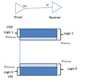
VOH(min) – Minimum Output High Voltage: This is the minimum voltage recognized as a 1 at the driving gate output. Anything above VOH(min) is recognized as 1. Anything less than this value is ‘indeterminate’ at this node, and causes functional issues for the circuit. VOL(max) – Maximum Output low voltage: This is the maximum voltage that can be recognized as a ‘0’ at the output of the driver. Noise causing the signal value to anything above this is a noise error scenario. VSS-VOL(max) range is a 0.
VIH(min) – Minimum Input high Voltage: This is the minimum voltage value that is recognized as a ‘1’ at the driven gate’s input. VIH(min)-VDD is range of values is recognized a ‘1’.
VIL(max) – Maximum Input low voltage: This is the maximum value that can be recognized as a ‘0’ at the receiving gate’s input. Any value in the VSS-VIL(max) range is a 0.
By definition, noise margins are:
NML (LOW NOISE MARGIN) = VIL(max) - VOL(max)NMH (HIGH NOISE MARGIN) = VOH(min) - VIH(min)
This ensures that if the driving gate voltage is at the maximum (minimum) allowed in case of 0 (in case of 1), the receiving gate can have a noise signal equal to the noise margin defined without affecting the circuit.