Spare Cells
Last modified 2012-11-23
Sini
I have been writing an article on ECO flows.Of course I cannot talk about freezesilicon ECOs without talking about spare cells.When I was a wee intern sitting through PnR training, spare cells confused me. I thought I had to insert the spares and use them in the same session! So here's a small note about spare cells.
Spare cells are just that.They are extra cells placed in your layout in anticipation of a future ECO.When I say future, I mean after you taped out and got your silicon back.After silicon tests complete, it might become necessary to have some changes to the design.There might be a bug, or a very easy feature that will make the chip more valuable.This is where you try to use the existing "spare" cells in your design to incorporate the design change.For example, if you need a logic change that requires addition of an AND cell, you can use an existing spare AND to make this change. This way, you are ensuring that the base layer masks need no regeneration. The metal connections have changed, and hence only metal masks are regenerated for the next fabrication.
Inserting Spare Cells
Spare cells need to added while the initial implementation. There are two ways to do this.
- The designer adds separate modules with the required cells. You start your PnR with spare cells included, and must make sure that the tool hasn't optimized them away. There can be more than one such spare modules, and they will be typically named spare* or some such combination. The inputs are tied to power or ground nets, as floating gates shouldn't be allowed in the layout. The outputs are left unconnected.
    //Definition
    module sparecells (  );
      INVX5 spareinv1 ( .A(1'b0) );
      INVX5 spareinv2 ( .A(1'b0) );
      DFFCPX2 sparedff2 ( .D(1'b0), .CP(1'b0), .CLR(1'b0), .PREZ(1'b1) );
      DFFCPX2 sparedff2 ( .D(1'b0), .CP(1'b0), .CLR(1'b0), .PREZ(1'b1) );
    endmodule
    //Instantiation
    sparecells sparei1 (  );
    sparecells sparei2 (  );
- Use a command provided by the PnR tool to add the spare cells to the netlist in placement stage. An example using ICCompiler command is given below.
    insertsparecells -libcell    {INVX5 \\
                                    DFFCPX2 \\
    		                } \\
                                    -cellname spare -numinstances 4 -tie -skiplegal
Spare Cell Placement
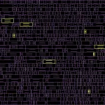
You need to give some thought as to where to place your spare cells in layout.They are not timing critical, and if you do not give any constraints, PnR tool will place them all together.However, you do not know which area of the layout will eventually require a connection to the spares.You can have two placement approaches.
-
Sprinkle the individual spare cells in your layout, so from any point you may have a reasonably close library cell.
-
Group the spare cells in multiple groups and sprinkle/place each group in the layout.

If the spare cells are included in the netlist, you need to set an attributesparecellso that the PnR tool does no optimize these. If you do not set them assparecellor set adont_touch, you will find that after placement all spare cells are gone.


Given below is an example of spare cell placement as grouped instances. Here it is assumed that the spare cells are instantiated in the netlist as sparei1 & sparei2.
	set physopt_tiesparecells true
	set_attribute \[get_cells  sparei\*/\*\] is_sparecell true
	spread_sparecells \[get_cells sparei1/\*\] -bbox \{\{30 30\} \{80 80\}\}
	spread_sparecells \[get_cells sparei2/\*\] -bbox \{\{300 100\} \{350 150\}\}
 	place_opt
And here's an example of inserting & placing spare cells using ICC. You can group the cells by giving cell names, which I haven't done below. It is sprinkled individually instead.
placeopt
set physopt_tiesparecells true
insert_sparecells -libcell    {INVX5 \\
                                DFFCPX2 \\
				} \\
                                -cellname spare -numinstances 2 -tie -skip_legal
legalize_placement -incremental
spread_sparecells \[getcells spare\*\] -bbox \{\{30 30\} \{350 150\}\}
psynopt
Note that I have used a command set physopt_tiesparecells true in the examples above. This ensures that the inputs are tied to TIE cells in the subsequent placement stage, instead of connecting directly to the power or ground lines. If you want to control the number of pins connected to a TIE cell, use the command setmaxfanout 1 libname/TIE* before running the above commands.